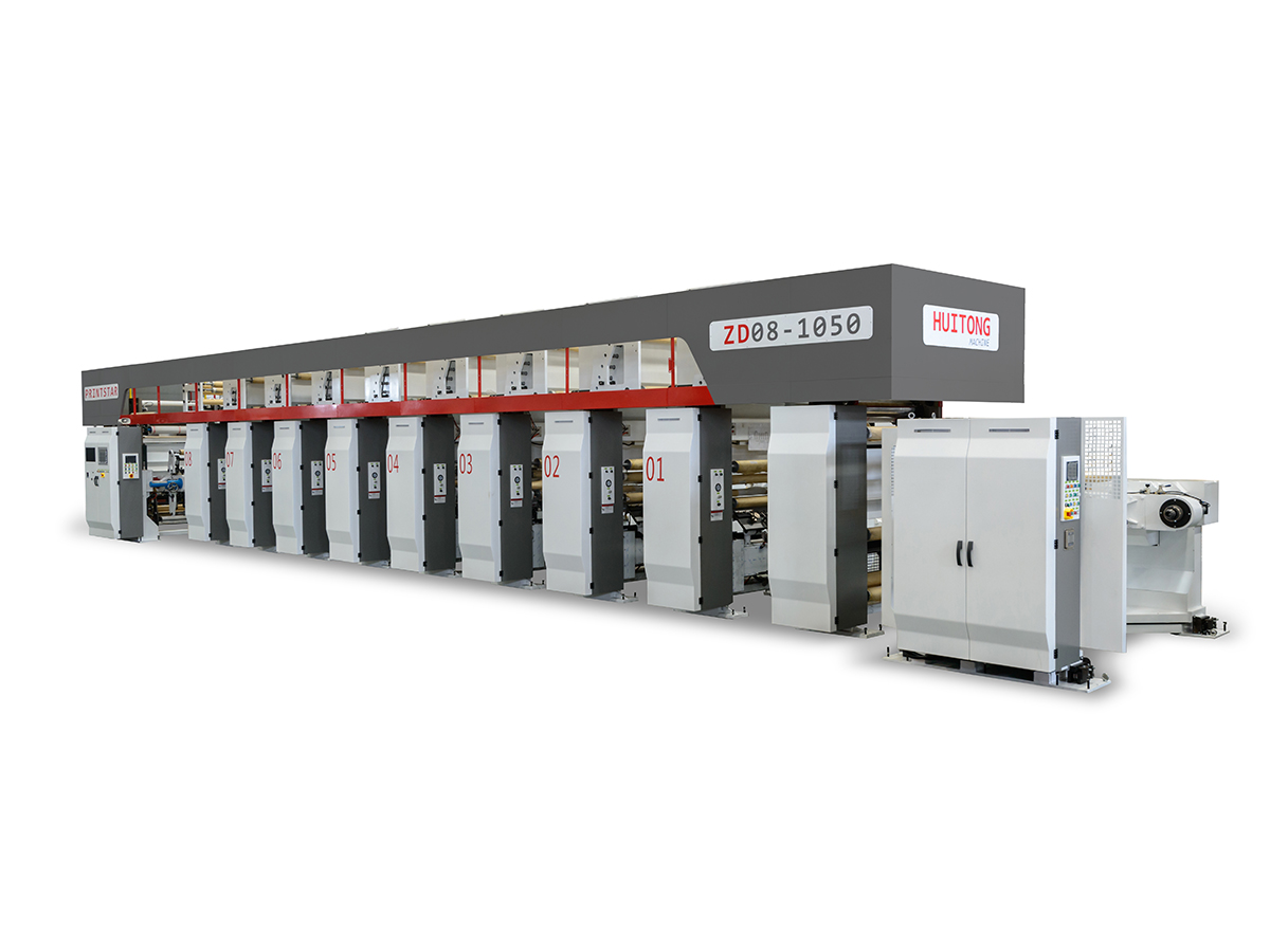
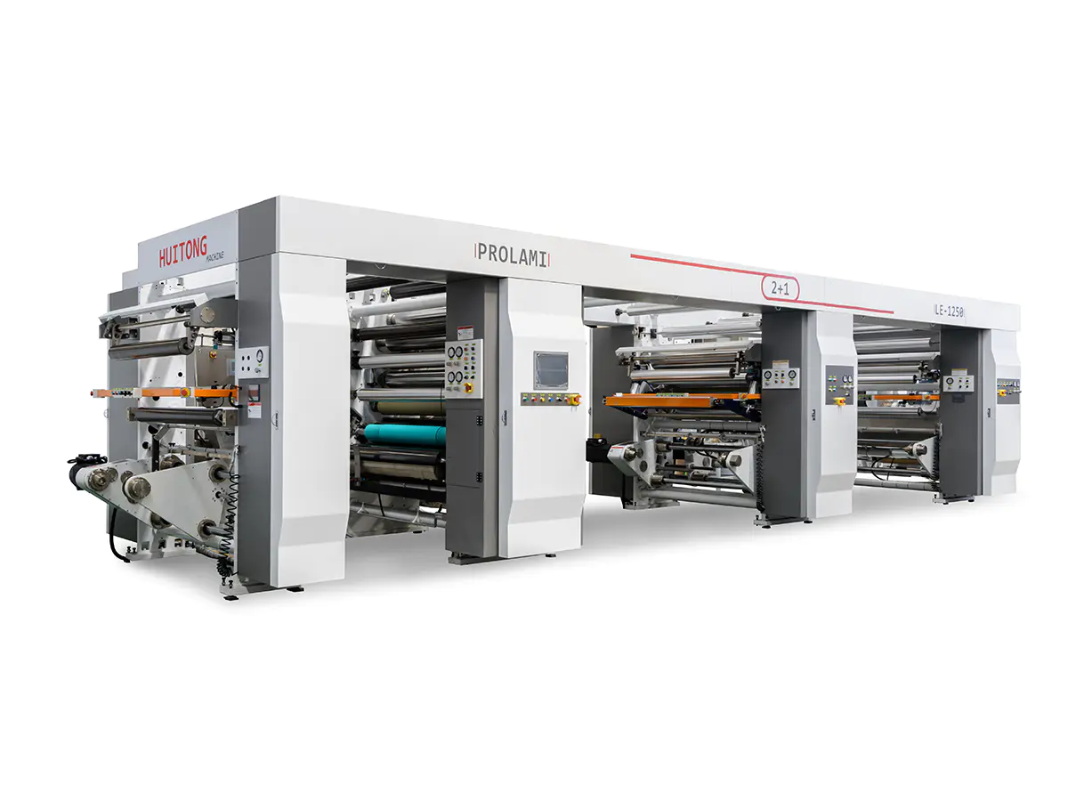
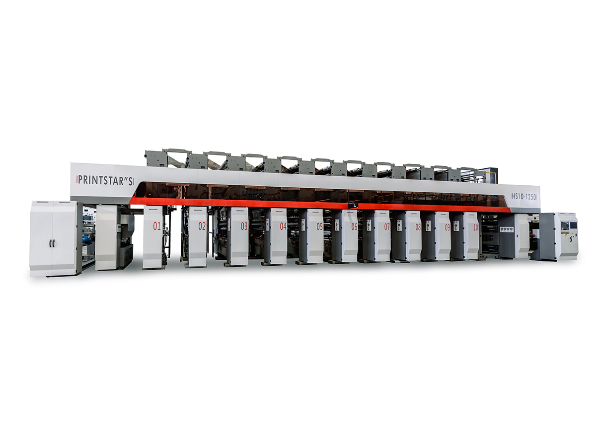
Print register accuracy determines whether a multi-color rotogravure job looks sharp or blurred. In a high speed rotogravure printing machine, each color station engraves and transfers ink independently, so even a fractional misalignment between cylinders can distort the final image. Automatic register control systems exist to correct this drift continuously, without operator intervention, keeping color separations locked in position across long production runs.
As press speeds climb past several hundred meters per minute, manual register adjustment becomes impossible to sustain. Web tension fluctuations, thermal expansion of cylinders, and material stretch all introduce variable errors that must be measured and corrected in real time. This is the operational gap that closed-loop register systems, including B&R register system architectures, are engineered to fill.
The B&R register system combines optical sensing, servo control, and software compensation into a single feedback loop. Its primary functions include:
These functions operate in a continuous cycle measured in milliseconds, allowing the system to respond to deviations before they become visible on the printed substrate.
The register correction cycle follows a consistent sequence regardless of substrate type. Understanding this flow helps operators diagnose issues faster when deviations occur.
Each cycle repeats continuously while the press runs, so register accuracy is maintained dynamically rather than checked only at fixed intervals.
| Component | Role | Typical Response Time |
|---|---|---|
| Optical Register Sensor | Detects printed marks on the moving web | Under 5 milliseconds |
| Servo Drive Unit | Adjusts cylinder rotational phase | 10 to 20 milliseconds |
| Tension Control Module | Stabilizes web tension across unwind and rewind | Continuous |
| Central Controller | Processes sensor data and issues correction commands | Real time |
Together these components form a closed loop that reacts to deviation before it accumulates into visible misregister, which is especially important on jobs with fine text or intricate line work.
A deviation of just a fraction of a millimeter between color stations can produce visible color fringing, blurred text edges, or halo effects around printed images, particularly on packaging with fine typography.
On a high speed rotogravure printing machine, register drift tends to worsen as speed increases because:
An automatic register control system compensates for all four factors simultaneously, which is difficult to achieve through manual adjustment alone.
Proper calibration is essential before a production run begins. A typical setup sequence includes the following steps:
Operators should recalibrate whenever substrate type, thickness, or cylinder set changes, since these variables directly affect tension behavior and mark detection accuracy.
| Symptom | Likely Cause | Recommended Action |
|---|---|---|
| Register mark not detected | Sensor misalignment or dirty lens | Clean sensor and recheck mark position |
| Oscillating correction | Tension instability | Recalibrate tension control module |
| Gradual drift over long run | Cylinder thermal expansion | Allow warm-up period before final calibration |
| Inconsistent correction between stations | Servo response mismatch | Check servo drive settings per station |
Most register issues trace back to sensor condition or tension inconsistency rather than the control logic itself, so routine sensor cleaning and tension checks resolve the majority of field problems.
Buyers comparing high speed rotogravure printing machine suppliers should evaluate register systems against a few practical criteria rather than marketing claims alone:
A system that performs well on lightweight film may behave differently on heavier paperboard, so requesting substrate-specific performance data during evaluation is a reasonable step before purchase decisions.
It corrects the alignment between color separations printed by different cylinders, adjusting for longitudinal and lateral deviation caused by tension changes, thermal drift, and material stretch during printing.
Correction typically occurs within milliseconds of detecting a deviation, allowing the system to respond before the error becomes visible on printed output.
Yes. Film, paper, and foil each stretch and respond to tension differently, so calibration should be adjusted whenever the substrate changes.
It cannot be fully eliminated, but a well maintained automatic system keeps deviation within an acceptable tolerance that is not visible to the eye during normal viewing conditions.
Recalibration is recommended whenever cylinders, substrate type, or job specifications change, and periodically during long production runs to account for gradual thermal effects.
Contact Us
Recommended Products
Joining Hands With Huitong
Customize Your Flexible Packaging Equipment Solution
Inquire now
Products
contact us

Tel: +86-0510-86328508
+86-0510-86324508
Mob: +86-13914908980
Email: [email protected]
ADD: No. 429 Xizhang Road, Gushan Town, Jiangyin City, Jiangsu Province, China

 English
 русский
 Español
 عربى
عربى